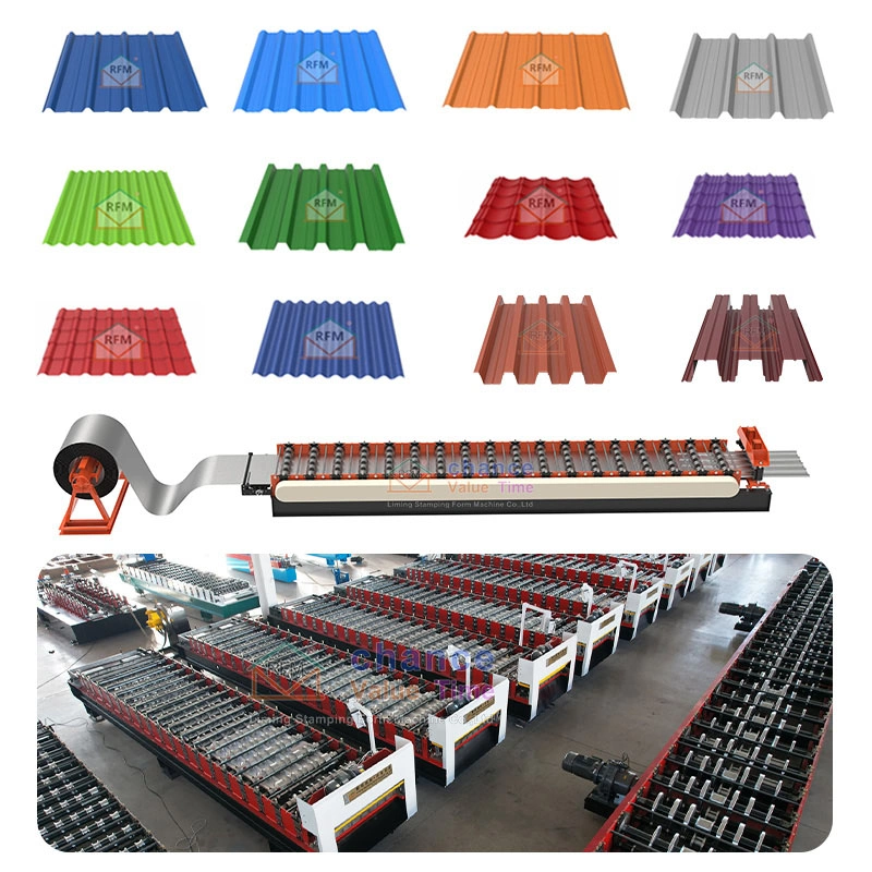
A roof panel roll forming machine converts flat metal coil into a continuous roofing profile through controlled feeding, progressive bending, length measurement, and cutting. The explanation of how does a roof panel roll forming machine work depends on the coordinated operation of the decoiler, forming stands, control system, and cutting unit. A properly designed roof panel roll forming process produces consistent cross-sections while protecting the surface of coated metal.
What Is a Roof Panel Roll Forming Machine?
A roof panel roll forming machine is a continuous metal-forming line that produces long corrugated, trapezoidal, standing-seam, or tile-effect roofing sheets. Successive pairs of rollers gradually shape the strip instead of producing the complete cross-section in one forming operation.
Roll forming changes the geometry of the strip without intentionally reducing its nominal thickness. The process is suitable for long products because the forming stands maintain a consistent cross-section while the material travels through the production line.
Why Continuous Forming Suits Roof Panel Production
Continuous forming supports repeatable profile dimensions, programmable panel lengths, and efficient batch production.
The production line can also integrate length measurement, cutting, punching, protective-film application, embossing, conveying, and automatic stacking.
What Happens During the Roof Panel Roll Forming Process?
The complete roof panel roll forming process follows seven connected stages:
- The decoiler supports and releases the metal coil.
- The feeding guide aligns the strip with the machine centerline.
- The forming stands create the profile through incremental bends.
- The calibration section stabilizes critical dimensions.
- The encoder measures the programmed panel length.
- The cutting unit separates the completed panel.
- The output system receives the finished product.
Step 1: Coil Loading and Controlled Decoiling
The decoiler carries the metal coil and releases the strip at a controlled rate. The required decoiler capacity depends on coil weight, coil width, inside diameter, outside diameter, and loading method.
A manual decoiler normally uses mechanical mandrel expansion. A hydraulic decoiler uses powered expansion and may include active rotation.
Stable decoiling reduces sudden tension changes that could disturb strip feeding or alignment.
Step 2: Feeding and Strip Alignment
The feeding unit positions the metal strip before the first forming stand. Adjustable side guides, entry rollers, or pinch rollers keep both strip edges correctly located.
Accurate entry alignment is essential because an initial offset can continue through the entire forming line. Poor alignment can contribute to unequal rib dimensions, damaged edges, panel drift, or longitudinal twist.
Step 3: Progressive Profile Formation
The main forming section contains a sequence of upper and lower roller sets. Each station completes only part of the total bending work.
Each following station moves the strip closer to the final roof panel cross-section. This progressive method distributes deformation across the production line and reduces excessive strain in individual bends.
The planned sequence of intermediate profile shapes is commonly called a flower pattern. The flower pattern considers:
- Bend angles and bend radii.
- Material thickness and yield strength.
- Rib height and profile depth.
- Profile symmetry.
- Longitudinal strain.
- Material springback.
- Contact between the rollers and strip.
The required number of forming stations therefore depends on the panel drawing and material properties rather than a universal specification.
Step 4: Profile Calibration
The final forming or calibration stations refine the most important panel dimensions.
These dimensions normally include:
- Effective coverage width.
- Rib height.
- Rib pitch.
- Side-lap geometry.
- Standing-seam dimensions.
- Panel flatness.
- Longitudinal straightness.
The calibration section improves dimensional stability, but it cannot compensate for every upstream alignment or tooling problem.
Step 5: Length Measurement and Automatic Cutting
An encoder or measuring wheel tracks the movement of the formed panel. The measuring device sends length data to the control system.
The control system compares the measured value with the programmed panel length. The system then activates the cutter when the target length is reached.
The cutting blade must match and support the finished profile. Incorrect blade geometry, excessive clearance, or inadequate panel support can deform the cut end.
Step 6: Finished Panel Discharge
The finished panel moves onto a support table, conveyor, or automatic stacking system.
Long roof panels require adequate support throughout the discharge stage. Insufficient support can allow the sheet to drag, bend, or strike nearby equipment.
What Are the Main Components of the Machine?
A complete roof panel line normally includes the following equipment:
- A manual or hydraulic decoiler.
- A feeding and guiding assembly.
- A rigid machine frame.
- Forming stands, shafts, bearings, spacers, and rollers.
- A motor, reducer, and transmission system.
- A hydraulic or servo cutting unit.
- A PLC control cabinet.
- An encoder, sensors, and touchscreen interface.
- An output table or automatic stacker.
Mechanical Forming Components
The machine frame supports the shafts and forming stands. Frame rigidity and shaft alignment influence the dimensional repeatability of the finished product.
The roller geometry controls rib height, pitch, bend radius, side-lap shape, and effective coverage width. The roller sequence also determines how gradually the material reaches its final shape.
Automation and Measurement Components
The electrical system coordinates feeding, forming, measuring, and cutting.
A typical control interface can display:
- Programmed panel length.
- Actual measured length.
- Target production quantity.
- Completed quantity.
- Current line speed.
- Operating status.
- Fault information.
Encoder slip or unstable measuring-wheel contact can cause finished-length errors. Accurate calibration and cutting synchronization are therefore essential.
Which Materials and Profiles Can the Machine Process?
Roof panel lines commonly process galvanized steel, pre-painted steel, aluminum-zinc-coated steel, and aluminum.
Roll-formed roof and wall cladding is widely manufactured from coated steel and aluminum coil. However, each machine must be designed for the selected material width, thickness, strength, and surface condition.
Material Properties That Affect Forming
Material thickness and yield strength influence bending progression, roller pressure, drive requirements, and springback.
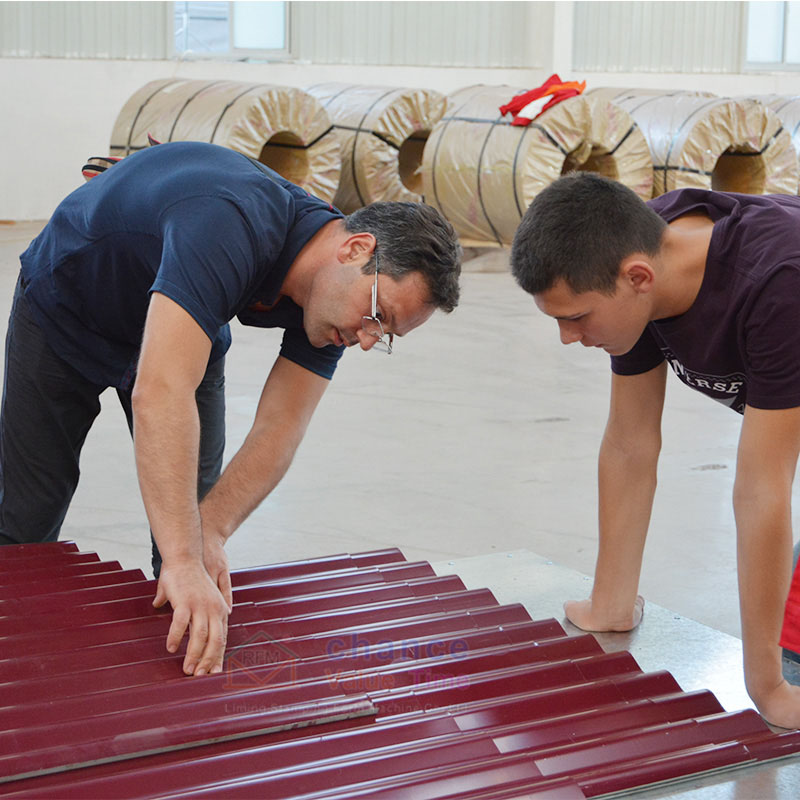
Pre-painted material requires smooth tooling, clean contact surfaces, and accurate strip alignment. Debris, excessive contact pressure, or uncontrolled sliding can damage the decorative coating.
Common Roof Panel Profiles
A dedicated production line can produce:
- Corrugated roofing sheets.
- Trapezoidal roof panels.
- Standing-seam panels.
- Tile-effect roofing sheets.
- Wall cladding panels.
Each profile requires a tooling sequence designed for its geometry. A fixed roller set cannot produce unrelated profiles without an additional forming level, replaceable cassette, or tooling change.
How Do Cutting Systems and Machine Configurations Differ?
Machine configuration affects production output, profile flexibility, floor-space requirements, and investment cost.
Pre-Cut and Post-Cut Systems
A pre-cut line separates the flat strip before the material passes through the complete forming section.
A post-cut line forms a continuous profile and cuts the panel after the final forming stand. Post-cut systems require blades that match the completed profile, while pre-cut systems must control the entry and exit behavior of individual blanks.
Stop Cutting and Flying Cutting
A stop-cut system pauses or slows the production line during the cutting stroke.
A flying cutter travels with the moving panel during cutting. This configuration can support higher net production speeds, although the system requires more precise motion control and synchronization.
Single-Layer and Multi-Layer Machines
A single-layer machine uses one dedicated forming level for one roof profile.
Double-layer and three-layer machines place separate roller sets within one machine structure. This configuration expands the available profile range without requiring several independent production lines.
The different forming levels normally operate separately rather than simultaneously.
Which Factors Determine Production Speed and Panel Quality?
Advertised forming speed does not equal actual production output.
Net output also depends on:
- Coil loading and threading time.
- Typical panel length.
- Cutting cycle time.
- Batch changes.
- Material discharge.
- Stacking capacity.
- Operator coordination.
- Line acceleration and deceleration.
Key Panel Quality Variables
Finished panel quality depends on several connected variables:
- The material must remain within the specified thickness and strength range.
- The entry guide must center the strip accurately.
- The shafts and forming stands must remain correctly aligned.
- The flower pattern must distribute strain appropriately.
- The encoder and cutting unit must remain synchronized.
- The discharge system must support the finished panel.
Research identifies springback, longitudinal bow, edge waves, twist, wrinkling, end flare, and surface scratches as relevant roll-forming defects.
How Does Safe Production Support Stable Operation?
The production area contains rotating shafts, in-running nip points, forming rollers, cutting points, and heavy coil-handling operations.
Machine guards must protect personnel from points of operation, rotating components, and ingoing nip points.
Trial Production and Process Verification
A trial panel allows trained personnel to verify:
- Effective panel width.
- Rib height and pitch.
- Side-lap fit.
- Panel straightness.
- Surface condition.
- Cut-end quality.
- Actual finished length.
The trial panel also confirms that the selected material, machine settings, and approved drawing are compatible before continuous production begins.
Which Information Defines the Correct Machine Specification?
A technically complete machine proposal depends on accurate project information.
The required data normally includes:
- The finished panel drawing.
- The effective coverage width.
- The feeding width.
- The material type and coating.
- The material thickness range.
- The material yield strength.
- The maximum coil weight.
- The coil inside and outside diameters.
- The target forming speed.
- The typical panel lengths.
- The required cutting method.
- The required length tolerance.
- The local voltage and frequency.
- The preferred automation level.
FAQ
Can One Machine Produce Several Roof Profiles?
A multi-profile machine can use separate forming layers, replaceable cassettes, or changeable roller tooling. Each profile still requires independently engineered roller geometry.
Does Roll Forming Reduce Sheet Thickness?
Conventional roll forming primarily changes the cross-sectional shape rather than intentionally reducing nominal material thickness. Localized strain still develops around the bends.
How Many Forming Stations Are Required?
The required station count depends on profile complexity, bend depth, material strength, material thickness, target speed, and dimensional tolerance.
What Causes Incorrect Panel Length?
Encoder slip, unstable measuring contact, incorrect calibration, material movement during cutting, and unsuitable control parameters can create panel-length errors.
Which Information Is Required for a Quotation?
A complete quotation requires the panel drawing, material specifications, coil dimensions, target speed, panel lengths, voltage, automation level, and cutting requirements.
Contact Hebei Liming for a Customized Roofing Line
Hebei Liming states that it has 30 years of experience in roll-forming machine design, development, and manufacturing. Its roofing equipment includes continuous production lines, high-speed configurations, automatic cutting, PLC control, and customized single-layer or multi-layer solutions.
Project teams can contact Hebei Liming through its website contact form, WhatsApp, or email and submit the panel drawing, material thickness, required speed, power supply, and automation requirements for a tailored configuration and quotation.